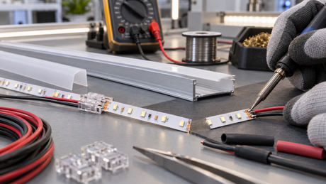
Direct answer: Neither a soldered joint nor a solderless LED strip connector is automatically the best choice for every commercial installation. A solderless connector can reduce assembly time and simplify replacement when it is correctly matched to the strip and remains accessible. A controlled soldered connection can be compact and mechanically secure, but its quality depends on pad preparation, heat control, insulation and strain relief. The correct decision must be based on the exact PCB width, pad layout, channel count, current, coating, profile space, environmental exposure and maintenance plan.
This guide is written for lighting designers, electrical contractors, installers, distributors and OEM buyers specifying low-voltage LED strip options for retail, hospitality, architectural, signage, display and commercial interior projects. It provides a system-level method for selecting and approving a connection without assuming that one connector, soldering process or installation detail is suitable for every LED strip model.
Why the Connection Method Matters
An LED strip connection is both an electrical interface and a mechanical transition. It carries current between a flexible PCB and a cable, another strip section, a controller or a power supply. It may also need to fit inside an aluminum profile, pass around a corner, resist cable movement and preserve the protection of a coated or encapsulated strip.
A poor connection can create intermittent operation, flicker, localized heating, color-channel loss or additional voltage drop. A joint that works during a brief bench test may still fail after installation if the cable pulls on the copper pads, the connector is too large for the profile, the contacts do not align with the pads, or the cut end is not resealed for the intended environment. Connection selection therefore belongs in the project specification, not as a last-minute site decision.
Connector or Soldering: The Short Comparison
| Method | Typical advantages and points to verify |
|---|---|
| Solderless connector | Faster field assembly and easier replacement when a compatible part is available. Verify PCB width, pad geometry, channel count, contact engagement, current rating, wire range, profile clearance, coating compatibility and environmental sealing. |
| Soldered connection | Compact and adaptable for custom wire exits or restricted spaces. Verify pad preparation, process control, conductor support, insulation, strain relief, operator consistency and protection of nearby LEDs and components. |
This table is a decision starting point, not a reliability guarantee. The completed connection must be approved with the actual strip, cable, load, profile and installation method.
Six Compatibility Checks Before Choosing a Connector
1. PCB width and overall strip thickness
A connector described only as “for LED strip” is not sufficiently specified. Its opening must match the actual flexible PCB width and thickness. A nominal width may not describe added coating, silicone or other encapsulation. For a strip installed in a profile, the connector housing and cable exit must also fit below the diffuser without forcing the strip away from the mounting surface.
2. Pad position, length and contact geometry
Connector contacts must land on the intended copper pads. A connector can appear to close correctly while a contact sits partly on solder mask, phosphor, silicone residue or the edge of a pad. Check pad length, pitch, exposed copper area and the location of nearby LEDs or components. This is particularly important for high-density or narrow PCB designs.
3. Number of conductors and electrical topology
Single-color strips commonly use two conductors, while tunable-white, RGB, RGBW and RGBCCT products require additional channels. Pad count alone is not enough: confirm the printed polarity, common connection and channel order. A mechanically compatible connector can still be electrically wrong if its contact arrangement does not match the selected strip and controller.
4. Current, voltage drop and temperature rise
The connector and its attached wire must be evaluated for the current in that branch, not only for system voltage. Every contact adds resistance. The resulting voltage drop is related to current and resistance, and the heat generated at a resistive point increases with current. Connector manufacturers therefore specify current capability and contact performance for defined products and test conditions; a generic appearance is not evidence of equal capacity.
For load planning, review the project together with the LED strip voltage-drop and power-supply sizing guide. Do not compensate for a weak connection by simply selecting a larger power supply. The connection, cable, feed arrangement and flexible PCB must all be suitable for the current they carry.
5. Coating, encapsulation and sealing method
An uncoated indoor strip, a coated strip and an encapsulated strip may require different preparation and connector designs. Removing coating carelessly can damage pads or reduce the protection intended for the strip. A connector fitted to an IP-rated strip does not automatically make the cut end or assembled joint suitable for the same exposure. Review the complete assembly using the LED strip IP-rating guide.
6. Service access and installation sequence
A replaceable connector has limited service value if it is buried behind finished joinery or sealed inside an inaccessible detail. Conversely, a permanent joint may be reasonable in a factory-prepared assembly when the installation provides strain relief and the complete sample has been approved. Decide where assembly, inspection and replacement will occur before choosing the connection method.
When a Solderless Connector Can Be the Better Choice
Solderless connectors can be useful for controlled field assembly, modular displays, replaceable shelf lighting, sample evaluation and projects where hot-work restrictions make soldering difficult. They can also standardize installation when the connector has been qualified for the exact strip construction and cable.
The key word is compatible. The housing should close without crushing the PCB or coating. Contacts should engage the full intended pad area. The cable should remain supported so that repeated movement is not transferred to the contact interface. The joint should fit inside the profile or enclosure without lifting the strip and creating a thermal or optical discontinuity.
For a commercial project, request the connector manufacturer’s relevant specifications and test the actual assembly under representative load. Current rating, conductor range, contact resistance, temperature limits and environmental suitability are properties of the specific connector system—not of solderless connectors as a general category. Connector engineering guidance from TE Connectivity distinguishes contact rating, resistance and retention as separate characteristics, while Molex connector guidance emphasizes voltage, current, vibration, environmental exposure and mating alignment.
When a Controlled Soldered Connection Can Be the Better Choice
Soldering may be considered when the connection must be compact, the cable exit is customized, a matching connector is unavailable, or a connector housing would create a visible gap or would not fit inside the selected profile. It can also be suitable for factory-prepared assemblies where process conditions and inspection are controlled.
Soldering is not automatically reliable merely because the joint is permanent. Excessive heat can lift copper pads, damage the flexible substrate or affect a nearby LED. Insufficient wetting, contamination or movement during cooling can create a weak joint. Too much solder can bridge adjacent channels. A cable soldered directly to the strip can tear the pad if the cable is allowed to carry mechanical load.
There is no universal soldering temperature or dwell time for every LED strip. Pad size, copper construction, surface finish, coating, solder alloy, wire size and tool geometry all affect the process. Use a documented process for the specific materials, inspect the joint, insulate it appropriately and provide strain relief beyond the soldered area. Published consumer guidance from Philips Hue also separates quick connector assembly from soldering as a permanent connection method; commercial projects should add their own product-specific qualification and installation controls.
Strain Relief Is Not Optional
Copper pads on a flexible PCB are electrical connection points, not cable anchors. Whether the joint is soldered or solderless, secure the cable so pulling, vibration, bending and installer movement are not transmitted directly to the strip. Consider the cable’s bend direction, the space available at the profile entry and the transition from flexible cable to flexible PCB.
Strain relief may be provided by the connector design, an approved clamp, a cable tie point, an enclosure feature or another documented method appropriate to the assembly. Adhesive tape alone should not be assumed to restrain an unsupported cable. After installation, the strip should remain flat on its thermal surface rather than being lifted by the connector or cable.
How Connections Affect Light Quality and Thermal Performance
A bulky connector can increase the spacing between illuminated sections and create a dark gap, especially in shallow profiles or continuous lines viewed at short distance. This should be evaluated with the actual diffuser and viewing condition. For COB and SMD selection around visible joints, refer to the COB versus SMD LED strip guide.
Electrical resistance at a poor joint can also create local heating and reduce the voltage available downstream. Separately, a connector that lifts the strip from an aluminum profile can interrupt the thermal contact path. The LED strip thermal-management guide explains why profile selection, contact and surrounding conditions must be evaluated as a complete system.
Outdoor and Damp Installations Need a Complete Sealing Plan
Do not describe a field-cut connection as waterproof merely because the original strip has an IP code. Cutting can expose conductors and create new paths at the end, cable entry or joint. The connection method, end sealing, cable gland, enclosure, drainage and installation orientation must be designed and validated for the intended exposure.
Also consider conditions that an IP code alone does not fully describe, such as ultraviolet exposure, cleaning chemicals, salt, condensation, thermal cycling and mechanical movement. Product and certification documentation, including UL, CE, RoHS and FCC documentation, is available across many Leomay product models; availability and relevance must be confirmed for the selected specification and target market.
A Representative Connection Approval Process
Freeze the materials: identify the exact strip, connector or solder process, cable, insulation, sealing materials, profile and diffuser.
Build the real geometry: reproduce pad alignment, cable exit, corner, profile clearance and strain relief.
Inspect before power: verify polarity, channel order, exposed conductors, insulation and mechanical engagement.
Operate under representative load: measure voltage before and after the joint and observe stability, color channels and local temperature behavior under the project’s operating condition.
Apply representative movement and environment: review cable handling, maintenance access and the exposure relevant to the project.
Document the approved assembly: record parts, tools, preparation, photos, acceptance checks and responsibility for site assembly.
The test plan should be agreed for the selected product and project. Avoid inventing one universal current limit, pull force, temperature rise or environmental test for all connections.
Common Connection Symptoms and What to Check
Intermittent flicker when the cable moves
Isolate power, then inspect contact alignment, connector closure, solder condition and strain relief. Movement-sensitive operation usually indicates that the electrical or mechanical interface needs correction rather than a random strip replacement.
One color channel is missing
Confirm the number and order of contacts, pad alignment, controller output and continuity of the affected channel. RGB, RGBW and tunable-white strips can illuminate partially even when one conductor is open.
The downstream strip is dimmer
Measure voltage across the joint under load and compare it with adjacent points. Also evaluate the cable length, conductor size, total current and feed layout. The connection may contribute resistance, but the complete current path must be assessed.
The joint or connector becomes unusually warm
Disconnect the circuit and check whether the connector is suitable for the actual current, wire and contact condition. Misalignment, incomplete engagement, damaged pads or excessive resistance can create local heating. Do not continue operating a visibly damaged or overheating joint.
For a wider system-level diagnostic workflow, use the commercial LED strip troubleshooting guide.
Frequently Asked Questions
Are solderless LED strip connectors reliable?
They can be reliable when the connector is designed for the exact PCB width, thickness, pad layout, channel count, current, wire and environment, and when it is correctly assembled and strain-relieved. A generic connector that merely fits over the strip is not sufficient evidence of compatibility.
Is soldering always better for a permanent installation?
No. A controlled soldered joint can be compact and durable, but poor heat control, inadequate wetting, damaged pads, missing insulation or cable strain can make it unreliable. Compare the actual soldered assembly with a qualified connector assembly for the project.
Can I use the same connector for SMD and COB LED strips?
Only if the connector is confirmed for the exact construction. PCB width alone does not prove compatibility. Check pad position, exposed contact area, strip thickness, coating, LED or phosphor clearance and the space required inside the profile.
How many pins does my LED strip connector need?
The connector needs contacts that match the strip’s electrical channels and common connection. Single-color, tunable-white, RGB, RGBW and RGBCCT strips use different arrangements. Confirm the printed pad labels and controller topology instead of selecting by pin count alone.
Does a connector add voltage drop?
Every connection has some resistance, so its voltage drop depends on current and contact resistance. A suitable, correctly assembled connector should be evaluated as part of the whole cable and feed path under representative load.
Can a connector fit inside an aluminum LED profile?
Some can, but clearance must be checked with the actual connector, cable exit, strip, profile and diffuser. The connector should not lift the strip, block the diffuser or create an unacceptable dark gap.
Does an IP-rated strip remain IP-rated after it is cut and connected?
Not automatically. Cutting creates new interfaces. The joint, end cap, cable entry and sealing process must be evaluated as a complete assembly for the intended exposure and applicable project requirements.
What information should I send for a connector or pre-wired sample review?
Send the selected strip or model, voltage, power or current per branch, PCB width, pad layout, color configuration, connector type, cable specification, connection quantity, profile dimensions, cable-exit direction, indoor or outdoor exposure, installation drawing, target market, required documentation and quantity range.
Specify the Connection as Part of the LED System
The most reliable connection is the one that has been matched to the exact strip and verified in the real assembly. Select solderless connectors for their installation and service advantages only when their electrical, mechanical and dimensional compatibility is documented. Select soldering for compact or customized connections only when the process, insulation and strain relief are controlled. In both cases, approve the completed joint under representative load, geometry and environment.
Planning a commercial LED strip, COB strip or silicone neon flex project? Send Leomay the application, installation drawing, selected strip or required specification, voltage, load, run lengths, connection locations, channel count, cable and profile constraints, environmental exposure, maintenance access, target market, required documentation and quantity range. Leomay can review relevant product and connection options for the selected model; final suitability and document availability must be confirmed for the specific specification and destination market.