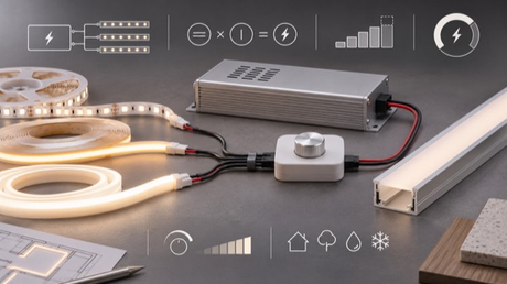
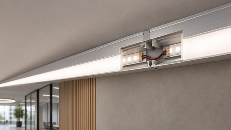
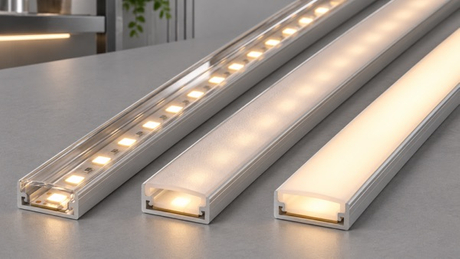
Choosing an LED power supply is not simply a matter of finding a wattage number larger than the LED strip load. A reliable specification must match the load type, output voltage or current, connected wattage, cable layout, control method, ambient temperature, enclosure and mains-side conditions.
For most voltage-rated LED strips and many LED neon flex products, the starting point is a regulated constant-voltage power supply with the same nominal output voltage as the lighting product. A genuinely current-driven LED load requires a compatible current-regulated driver and an operating voltage range that contains the load voltage. However, a strip described as “constant current” may use current-regulating components on the strip while still accepting a fixed-voltage input. The exact input specification and wiring diagram—not the category words “constant current,” “COB,” “SMD” or “neon”—must decide which external power supply is correct.
This guide explains the decisions that lighting buyers, designers, installers and procurement teams should make before approving an LED strip power supply. It also shows why a fixed “20% spare capacity” rule cannot replace the driver manufacturer’s load limits, derating curves and installation instructions.
Use this order:
Identify the exact LED load and whether it requires constant voltage or constant current.
Match the required output voltage or regulated current.
Calculate the maximum connected load for each circuit and control zone.
Check the driver’s permitted load range, ambient-temperature rating and derating conditions.
Decide how dimming or control will be implemented.
Check cable length, feed points and controller capacity separately from driver wattage.
Confirm the installation environment, accessibility, ventilation and ingress protection of the complete assembly.
Check mains input, inrush current, protective-device coordination and project documentation.
A driver is correctly specified only when all eight decisions are compatible.
The selection process is particularly important for:
lighting designers specifying continuous linear light;
electrical engineers and contractors planning circuits and control systems;
distributors comparing technically similar power supplies;
OEM and project buyers preparing an approved component list;
sign makers and display builders using LED strip or neon flex;
joinery, retail and hospitality teams integrating light into confined spaces;
buyers working on European projects where documentation and system interoperability must be verified before approval.
The goal is not to nominate one universal driver. It is to create a specification that can be checked against a real LED load, a real installation and a real driver datasheet.
Before comparing drivers, collect the load information for every connected lighting section:
product type and exact model;
constant-voltage or constant-current requirement;
nominal voltage or rated current;
rated watts per metre, watts per module or total rated power;
total installed length and maximum continuous run length;
single-colour, tunable-white, RGB, RGBW or pixel/control architecture;
expected simultaneous channel operation;
cable length, conductor size and feed arrangement;
indoor, damp, outdoor or enclosed installation;
required dimming or building-control interface.
Do not select a driver from the LED family name alone. Two COB strips may have different voltages and power densities. Two neon flex products may have different feed arrangements, bend directions, ingress-protection constructions and maximum run lengths. The electrical data on the exact product must govern the decision.
The distinction describes what the driver regulates.
| Driver type | What remains regulated | What the load must match | Typical label pattern | Common application logic |
|---|---|---|---|---|
| Constant voltage (CV) | Output voltage | Load voltage must equal the driver output voltage | 12 V DC, 24 V DC or another fixed DC voltage, plus a maximum current/power | Common for voltage-rated LED strips and many LED neon flex products |
| Constant current (CC) | Output current | Rated current must match; load voltage must fall inside the driver’s operating voltage window | A fixed current such as 350 mA or 700 mA, plus an output-voltage range | Common for current-driven LED modules and luminaires |
| Multi-mode or combined characteristics | Depends on design and operating region | Must be checked against the exact datasheet | May show both voltage and current limits | Do not assume compatibility from headline wattage |
For a voltage-rated strip marked 24 V DC, a 24 V constant-voltage supply is normally the correct electrical category. A 12 V supply will not provide the intended operating condition, and a higher output voltage can damage a 24 V load.
For a current-driven LED module, matching only total watts is not sufficient. The regulated current must match the module requirement, and the module’s operating voltage must sit within the driver’s stated output-voltage range.
Be careful with the phrase “constant-current LED strip.” In some strip designs it describes regulation built into the strip, not the required output mode of the external supply. If the strip input is specified as a fixed DC voltage, select and wire the external supply according to that verified input requirement. Do not infer the external driver type from the category name alone.
If the product label is unclear, stop and obtain the datasheet before energising the system.
With a correctly matched constant-voltage system, the power supply’s current rating is its maximum available capacity; it does not normally force that full current into the strip. The connected load draws current according to its electrical design at the applied voltage.
For example, a 24 V load requiring 3 A can operate from a properly regulated 24 V supply rated for more than 3 A, subject to the driver’s permitted load range and installation conditions. The critical match is the output voltage. Available current must be sufficient, but a higher current capacity is not the same as applying a higher voltage.
This principle must not be transferred blindly to constant-current systems. In a constant-current circuit, the driver actively regulates current, so the specified current is a primary compatibility value.
For a simple single-colour constant-voltage strip:
Connected load (W) = rated watts per metre × connected length in metres
Output current (A) = connected load (W) ÷ nominal voltage (V)
This is a calculation example, not a Leomay product specification.
A 24 V strip is rated at 9.6 W/m and one circuit contains 7.5 m:
Connected load = 9.6 W/m × 7.5 m = 72 W
Output current = 72 W ÷ 24 V = 3 A
The next step is not to select a driver from 72 W alone. Check the candidate driver’s allowed loading, ambient-temperature limits, derating curve, enclosure conditions, dimming method and expected operating duty.
For tunable-white, RGB and RGBW systems, establish which channels can operate simultaneously and how the product’s published power rating is defined. Also check:
total controller output capacity;
current limit per channel;
total current limit across all channels;
common-positive or other wiring architecture;
whether repeaters or amplifiers are required;
whether dynamic effects create a different practical maximum than a static scene.
Do not multiply a single-channel value by the number of channels unless the product documentation states that this represents the maximum simultaneous load.
Designers often apply a fixed spare-capacity rule, commonly described as 10%, 20% or 25%. A margin can be useful, but no single percentage is correct for every driver, temperature and installation.
The usable capacity may change because of:
maximum ambient temperature;
sealed or poorly ventilated enclosures;
driver mounting orientation and spacing;
input-voltage conditions;
manufacturer derating curves;
continuous duty versus intermittent scenes;
dimming behaviour and controller losses;
cable and connection losses;
future extensions that are genuinely included in the design.
A better method is:
Calculate the realistic maximum connected load.
Check the driver’s permitted output range and any minimum-load condition.
Apply the manufacturer’s derating instructions for the actual ambient and enclosure.
Allow project headroom only after those limits are understood.
Record the assumptions in the circuit schedule so that future changes can be reviewed.
Oversizing without analysis is not automatically safer. A much larger driver may have different physical dimensions, minimum-load behaviour, standby characteristics, acoustic behaviour, cost or inrush current. Select the appropriate operating window, not the largest available wattage.
A driver can have sufficient output wattage while the far end of the strip still appears dimmer or changes colour. The cause may be voltage drop in the strip conductors, extension cable, connectors or control equipment.
Voltage-drop planning is a separate task. It may require:
shorter feed paths;
larger cable conductors;
centre feeding or feeding from both ends where the product allows it;
multiple feed points;
shorter controlled zones;
power injection for addressable systems;
a suitable 24 V product instead of 12 V when the exact application supports that choice.
Do not increase the supply output voltage above the LED product rating to compensate for a poor distribution design. For a deeper treatment, see LED Strip Voltage Drop and Power Supply Sizing: A Practical Guide for Commercial Projects.
One high-capacity driver may reduce the number of components, but several smaller drivers or zones can improve distribution and serviceability. Compare both architectures before approval.
| One larger driver | Several smaller drivers or zones |
|---|---|
| Fewer driver locations | Shorter low-voltage distribution paths may be possible |
| Potentially simpler component count | A fault may affect a smaller area |
| Requires careful current distribution and branch protection | Easier phased maintenance or scene grouping |
| May create higher inrush at one point | Inrush may be distributed, but cumulative effects still require checking |
| A single failure can affect a larger illuminated area | More components and accessible mounting locations are required |
The choice should consider fault impact, cable routes, control zones, access, maintenance strategy, protective devices and the maximum permitted run length of the LED product—not only purchase price.
“Dimmable” is not one universal interface. The control signal, driver and LED load must form one compatible chain.
The mains power supply produces fixed DC output. A compatible controller switches or modulates the low-voltage output to control one or more channels.
Check the controller’s input voltage, per-channel current, total current, switching frequency, wiring architecture and compatibility with the selected strip.
The driver accepts a supported dimming input and changes its output accordingly. Verify the exact dimming method, control range, minimum level, off behaviour and compatibility with the control device.
DALI, 0–10 V, phase-cut/TRIAC, DMX and other systems are not interchangeable. A gateway, decoder, dimmable driver or low-voltage controller may be required between the building signal and the LED strip.
The term on the project specification must match the actual interface supported by every component. For a protocol-by-protocol decision guide, see How to Choose LED Strip Dimming and Control: PWM, 0–10V, DALI, DMX or TRIAC?.
The driver environment affects both safety and usable output.
Confirm ventilation, clearances, mounting instructions and access for replacement. Do not bury serviceable components where they cannot be inspected or replaced.
Measure or estimate the real ambient temperature. A confined cavity can be warmer than the occupied room. Check combustible-material restrictions, cable routing, ventilation and the driver’s temperature limits.
An ingress-protected driver inside another sealed box can still overheat. The outer enclosure changes heat dissipation. Use the driver manufacturer’s derating data and evaluate the complete assembly.
The IP rating of one component does not make the whole system suitable for outdoor use. Review the driver, LED product, connectors, cable entries, joints, drainage, mounting orientation and exposure together. Condensation and standing water need separate consideration.
Plan where the driver, controller and connection points will be reached after ceilings, cabinets, signage or façades are complete. An electrically correct but inaccessible installation creates avoidable maintenance cost.
Output wattage is only one side of the driver. The mains-side design must also consider:
input-voltage and frequency range;
maximum input current;
inrush current and its duration;
the number of drivers switched together;
protective-device type and rating;
upstream relays, contactors and control devices;
power factor and harmonic requirements where applicable;
earthing, insulation class and system safety architecture;
emergency-lighting or central-control compatibility if required.
Inrush current is especially important when many LED drivers energise simultaneously. A circuit may trip at switch-on even though its normal running current appears acceptable. The responsible electrical designer should use the selected driver’s published inrush data and local installation requirements to determine circuit grouping and protective-device coordination.
For European projects, also confirm the documentation and declarations required for the specific driver, luminaire assembly and market. Do not treat a logo, reseller description or family-level statement as proof that the exact selected model satisfies every project requirement.
The LED construction affects optical and mechanical decisions, but it does not replace the electrical specification.
COB describes the light-emitting construction. To select a power supply, still use the exact strip voltage, watts per metre, length, feed arrangement and control method. A COB strip does not automatically require a special driver simply because it is COB.
SMD strips vary widely in voltage, power density, LED density, channel count and control type. Read the exact datasheet and calculate the circuit load.
Neon flex adds mechanical and environmental considerations such as bend direction, end-entry or side-entry cable, connector sealing, mounting channel, thermal conditions and maximum run length. These can change feed locations and driver placement even when the underlying electrical system is constant voltage.
For every category, the correct question is: What are the verified electrical and installation requirements of this exact product and this exact run?
An aluminium LED profile can support strip mounting, heat transfer and optical diffusion. It does not automatically make the profile a suitable enclosure for the power supply.
Check:
strip PCB width versus internal profile width;
connector and solder-joint clearance;
diffuser clearance and optical depth;
thermal contact between strip and profile;
cable exit space;
profile accessibility after installation;
whether the driver has a separately approved and ventilated location.
Do not place a driver inside an aluminium profile or small cavity unless the component design, temperature limits, clearances and service strategy have been verified for that arrangement. For mechanical fit, see LED Strip and Aluminum Profile Compatibility: A Practical Guide to Width, Heat and Diffusers.
Include the following fields in a request for quotation or technical submittal:
| Field | Information to provide or verify |
|---|---|
| LED load | Exact product/model, voltage or current requirement, W/m and total length |
| Circuit design | Number of runs, length per run, feed points and cable lengths |
| Output requirement | CV voltage or CC current plus required operating range |
| Maximum connected load | Watts and amps per driver or zone |
| Control | Non-dim, PWM, DALI, 0–10 V, phase-cut, DMX or other defined interface |
| Environment | Indoor, damp, outdoor, cavity, sealed enclosure and expected ambient temperature |
| Mains input | Country/region, voltage, frequency and switching arrangement |
| Installation | Driver location, ventilation, mounting, access and cable-entry conditions |
| System limits | Controller current, cable voltage drop, maximum run length and branch protection |
| Project documents | Exact model datasheet and any required model-specific declarations or test documents |
| Maintenance | Access method, replacement strategy and fault-zone impact |
This information is more useful than asking only for “a power supply for 10 metres of LED strip.”
The numbers below are hypothetical and are provided only to show the decision process.
Strip rating: 12 W/m
Total installed length: 8 m
Connected load: 96 W
Nominal output current: 96 W ÷ 24 V = 4 A
The buyer must then check whether the 8 m is one permitted continuous run or should be divided into feeds, calculate cable voltage drop, select an appropriate driver operating window, apply temperature/enclosure derating, and confirm whether dimming occurs in the driver or through a downstream controller.
Three zones with separate scene control
Each zone has its own strip length and cable route
All zones may operate simultaneously
Instead of adding all watts and selecting one large driver immediately, compare:
one driver plus a correctly rated multi-zone controller and protected branches; and
separate drivers/controllers near each zone.
The second option may reduce low-voltage cable length and limit the effect of one failure. The first may reduce component count. The better choice depends on the real cable routes, control system, maintenance access, inrush and fault strategy.
| Symptom | Possible causes to investigate |
|---|---|
| Strip does not light | Wrong output voltage/current type, polarity, wiring, control signal, protection mode or failed connection |
| Driver cycles on and off | Overload, short circuit, overheating, incompatible load or protection-mode behaviour |
| Far end is dimmer | Voltage drop, excessive run length, cable size, connector loss or insufficient feed points |
| Flicker at low dim level | Driver/controller incompatibility, minimum-load behaviour, control-signal quality or dimming-range limit |
| Breaker trips at switch-on | Cumulative inrush, circuit grouping or protective-device coordination |
| Driver runs unusually hot | High ambient temperature, sealed enclosure, overload, inadequate spacing or unsuitable mounting |
| Different zones do not match | Unequal cable drop, different loads, controller settings, product variation or inconsistent feed design |
| Radio/audio interference appears | EMC interaction, cable routing, control frequency, grounding or component compatibility |
Troubleshooting should begin with measured voltage/current and the exact component datasheets. Replacing a driver with a larger wattage model without identifying the cause can leave the real fault unchanged.
Driver manufacturers publish model-specific information that a general guide cannot replace. For example, the MEAN WELL LED driver technical FAQ explains CV/CC operating regions, overload behaviour and system-level EMC considerations, while Signify’s driver-selection guidance shows which label information is needed to distinguish and replace CV and CC drivers.
Use such references to understand the selection method, but use the datasheet, installation instructions and declarations for the exact selected model as the final technical evidence. Requirements and operating limits must not be transferred from one series, wattage or enclosure type to another.
Most strips labelled with a fixed DC input voltage, such as 12 V or 24 V, use a constant-voltage supply at the same voltage. Some products described as “constant-current strips” contain onboard current regulation but still accept fixed-voltage input; other LED loads genuinely require a constant-current driver. Always follow the exact input specification and wiring diagram.
Multiply the verified watts per metre by 5 m, then check output voltage, maximum run length, driver load range, derating, environment, dimming and cable design. Length alone is not enough because different strips can have very different power densities.
In a correctly matched constant-voltage system, the current rating is available capacity; the load draws what it requires. The output voltage must match. Constant-current systems work differently, so the regulated current must match the load requirement.
No universal percentage replaces the selected driver’s datasheet. Calculate the real load, then consider the manufacturer’s load range, ambient-temperature derating, enclosure, duty, controller losses and project expansion. Document the chosen margin and why it is appropriate.
Yes, if the output type and voltage match, the total load is within the permitted operating range, branches and controllers are correctly rated, and voltage drop is controlled. Fault isolation and maintenance access should also be considered.
The likely issue is voltage drop or an excessive continuous run, not total driver wattage. Review the strip limit, cable length and size, connectors and feed-point layout.
No. The dimming interface, driver output, controller and LED load must be compatible. PWM, DALI, 0–10 V, phase-cut and DMX describe different control approaches and may require additional components.
Not solely because they are COB. Select the supply from the exact strip voltage or current requirement, power density, length, feed design and dimming architecture.
The complete installation must be suitable for the exposure. Review the driver location and rating, connectors, joints, cable entries, drainage, mounting and condensation risk. One IP-rated component does not protect the whole system.
Only if that exact arrangement is permitted and thermally suitable. Most profile decisions concern the strip and diffuser; the driver still needs verified clearances, ventilation, temperature conditions and service access.
LED drivers can draw a short inrush current at energisation. The cumulative inrush of multiple drivers can affect protective devices, relays and contactors even when normal running current is acceptable. Use model-specific inrush data in the mains-side design.
Send the exact LED product, voltage/current requirement, W/m, length per run, number of zones, cable lengths, control method, input mains, installation environment, ambient temperature, driver location and required project documents.
A robust LED strip system is a chain: mains input, driver, controller, cable, connectors, LED load, thermal path and installation environment. Each link must be compatible with the others.
Leomay’s confirmed product scope includes LED strip, COB strip, silicone neon flex and aluminium LED profiles. To discuss a project, send the verified load data, run lengths, cable layout, control method and installation environment through the Leomay contact page. You can also review the available categories on the Leomay products page.
The more complete the application information, the more precisely the component options and compatibility questions can be reviewed before installation.