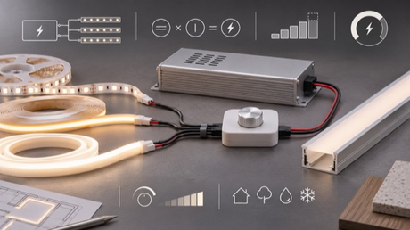
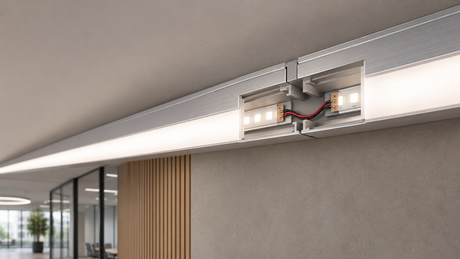
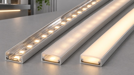
Quick answer: A long linear light should not be treated as one oversized strip, one oversized profile and one oversized diffuser. It is a coordinated assembly of mechanical sections, optical sections and electrical circuits. Plan where the aluminum profiles meet, where the LED strip is cut and bridged, where the diffuser is divided, where power enters and how each section can later be accessed. The best layout keeps these decisions related—but not automatically stacked at the same point.
Long illuminated lines look simple after commissioning. During design and installation, however, they combine materials that move, bend, heat and age differently. The substrate may not be perfectly straight. Aluminum profiles expand and contract. Diffusers can show seams or stress. LED tape has fixed cut points, while cables and connectors require space. A joint that is acceptable mechanically may still create a dark line optically or an inaccessible failure point electrically.
This guide explains how specifiers and installers can plan long LED strip or COB strip runs inside aluminum profiles without relying on a universal maximum length or expansion gap. Those values depend on the selected strip, profile, diffuser, driver, ambient conditions and installation method. The objective is better system architecture: controlled joints, predictable light continuity and practical maintenance.
This article is for lighting designers, architects, electrical contractors, shopfitters, joinery manufacturers, signage manufacturers, distributors and OEM buyers. It is especially relevant to long recessed, surface-mounted or suspended linear runs in retail, hospitality, offices, residential joinery, display systems and architectural details.
The search intent is mixed. Designers ask whether a continuous line can cross several profile sections. Installers need a reliable method for joining channels and routing wires. Procurement teams need to know which drawings and component details must be confirmed before ordering. Facility teams care about replacing one failed section without dismantling an entire ceiling or wall.
Most joint problems begin when the installation is designed as a visual line but not as an assembly. Four systems are forced to share one joint without checking their individual requirements:
Building interface: the ceiling, wall, cabinet, shelf or floor detail supporting the installation.
Mechanical carrier: aluminum profiles, mounting clips, brackets and fixing points.
Optical layer: diffuser, LED pitch, profile depth and emitter-to-cover distance.
Electrical layer: LED sections, cut points, flexible links, feed cables, drivers, controls and service connections.
If these layers are not coordinated, one correction creates another defect. Pulling two profile sections tightly together may improve alignment on installation day but leave no accommodation for movement. Bridging the joint with continuous LED tape may hide a dark zone initially but expose the circuit board to mechanical stress. Placing a bulky connector below the diffuser may improve serviceability while creating a visible shadow.
Start with the actual substrate, not the ideal CAD line. Identify changes in material, structural movement joints, access panels, ceiling modules and tolerances in joinery or drywall. A straight aluminum run cannot compensate for a substrate that changes level or direction without a planned transition.
Fixing strategy affects movement. A long profile constrained at every point behaves differently from one installed with a defined reference point and controlled movement elsewhere. The correct detail must follow the selected system, orientation and project conditions.
Map available profile lengths onto the architectural run and choose joint locations before cutting. Keep joints away from focal points, tight curves, end caps and wiring congestion where possible. Use suitable alignment components or a controlled site method to keep sections level, straight and rotationally consistent.
Do not assume every butt joint should be forced closed permanently. Aluminum changes length with temperature, while surrounding materials may move differently. Required allowance is project-specific and should be confirmed for the profile, fixing method, total run and expected temperature range.
The diffuser joint does not always need to coincide with the aluminum joint. Staggering them can reduce the appearance of one transverse seam, but only if the cover can be installed and removed safely. A continuous cover across multiple sections may improve appearance in some systems, yet complicate movement and access. Follow the selected cover system rather than assuming longer is always better.
Optical continuity depends on LED pitch, profile depth, diffuser transmission, internal cable shadows and the distance from the last emitter on one section to the first emitter on the next.
Divide the circuit according to valid cut points, electrical loading, voltage-drop calculations, driver capacity, control zones and service access. A profile joint is not automatically a valid LED cut point. An electrical division does not have to sit directly below the profile joint if a flexible bridge can be routed safely.
As a default engineering principle, do not automatically bond continuous LED strip rigidly across a profile joint. Two sections can move relative to each other during transport, installation and temperature cycles. Flexible printed circuit adhered across that interface becomes an unintended mechanical link, concentrating stress at copper tracks, solder pads or components.
A more controlled method is to cut only at a permitted mark and reconnect the sections with a flexible electrical bridge that includes appropriate movement reserve. The bridge should not be tight, pinched by the diffuser or placed where it casts an obvious shadow. Conductor size, insulation, polarity and connection method must match the selected circuit and environment.
This does not mean every assembly must be cut at every joint. Some systems use factory connectors or dedicated joiners. The principle is to prevent the LED circuit board from becoming a structural expansion link.
A reliable joint plan answers five questions before installation:
Where will each aluminum section start and end?
How will adjacent sections be aligned in height, direction and rotation?
Where can movement occur without an unacceptable visual gap?
How will the LED circuit cross or bypass that joint?
Can the diffuser and internal connection be accessed later?
Do not copy a gap dimension from an unrelated product. Movement depends on total length, aluminum temperature, ambient variation, solar exposure, mounting restraint and surrounding materials. Indoor joinery, a sun-exposed detail and a refrigerated display are different conditions even if the visible profile looks similar.
For recessed installations, coordinate recess width and edge finish with the joint plan. For suspended installations, joint stiffness and suspension spacing affect level. For surface-mounted profiles, clips and fixing holes must not pull adjacent sections into a step.
A continuous diffuser can conceal a profile joint and reduce transverse seams. It may suit systems that permit the cover to cross a joint, when the path is straight and there is enough access to install it without excessive bending. Transport, handling and future removal must also be considered.
Shorter sections are easier to transport, replace and coordinate with access zones. Their seams require square cuts and accurate alignment. A poor cover joint can create a bright edge, dark line or change in diffusion even when the LEDs below are continuous.
Test the actual profile, diffuser and LED arrangement at the intended viewing distance. A seam obvious on a workbench may disappear from the floor, while a small internal cable can create an unexpected shadow.
Control emitter spacing: keep the distance across the bridge consistent with the strip's visual rhythm.
Use valid cut points: cutting elsewhere can damage the circuit and create an irregular end zone.
Keep links low and tidy: wires near the diffuser can cast shadows.
Maintain alignment: a vertical step changes diffuser distance and apparent brightness.
Check diffuser ends: angled or compressed ends refract light differently.
Test real dimming levels: differences may be more visible at low output.
COB LED strip can reduce visible light points, but it does not eliminate joint design. The last luminous segment before a cut and the first after the bridge still need a balanced transition. A deeper profile and high-diffusion cover can improve blending, but also change output and appearance. Select from an illuminated sample, not from the word “dotless” alone.
A long visual line does not have to be one electrical run. Dividing it into planned circuits can improve voltage control, commissioning and maintenance. Calculate load and voltage drop using actual strip power, voltage, conductor length, conductor size and feed arrangement. Confirm drivers and controls against the selected strip and project requirements.
Feed points may be at one end, both ends, intermediate positions or separate zones, depending on calculation and instructions. Do not infer allowable run length from voltage alone. Two strips with the same nominal voltage may have different power, copper construction, cut length and feed recommendations.
Map cable routes before finalizing the profile. A recessed channel with no cable entry at the feed point may force drilling after finishing or create visible wiring. Label circuit direction and polarity. If sections use separate drivers or controls, identify zone boundaries on drawings and at accessible connection points.
Width compatibility is only the first check. The strip may fit the profile while its connector, solder joint or cable bend does not. Check usable internal width after retaining features and screw heads; height below the diffuser; cable bend space; clearance from sharp edges; connection shadows; access for replacement; and environmental protection at the joint.
Very slim profiles leave little room for connectors. If a removable connector is required, the assembly may need a wider cavity or dedicated non-luminous service zone. Soldered bridges still need strain relief and insulation space.
A corner changes mechanical alignment, optical spacing and cable routing at once. For a mitred corner, determine whether the diffuser is mitred, butt-jointed or stopped before a corner element. Ensure the strip can follow its permitted bend or divide it into valid sections linked flexibly. Do not crease strip to force a sharp direction change.
At T-junctions, decide which line is visually dominant and where each seam terminates. Calculate electrical branches rather than assuming equal-looking arms have equal load. At wall-to-ceiling transitions, allow for different substrates and access on each plane.
If the design requires a continuous luminous curve, LED neon flex or another suitable flexible solution may be better than forcing rigid profiles around the geometry. Bend direction, bend radius, cutting and connection rules must be confirmed for the selected model.
Serviceability is a design feature. Confirm whether one diffuser section can be removed without disturbing the full run, one LED section can be disconnected at an accessible point, drivers and controllers can be reached, cable joints remain accessible, and a replacement section can be installed without changing adjacent appearance.
Long runs benefit from section IDs. Mark profiles, circuits, feed points, driver locations and control zones consistently on drawings and during installation. Photograph concealed routes and connections before closing covers.
A short sample confirms color, diffusion and basic fit but may not reveal real joint conditions. A long-run mockup should include a representative profile joint, LED bridge or connector, intended diffuser joint, real feed entry and planned mounting method.
Review it from the normal viewing position and at expected dimming levels, both switched off and illuminated. When off, profile and diffuser alignment dominate. When illuminated, emitter spacing, internal shadows and cover seams become more important.
Profile sections are straight, level and aligned.
Movement allowance follows the selected system and project conditions.
LED tape does not act as a rigid bridge across moving sections.
Links have correct polarity, insulation, capacity and movement reserve.
Feed points match voltage-drop and driver planning.
No connector, wire or fixing creates an unacceptable shadow.
Diffuser joints are square, aligned and removable.
Corners maintain acceptable luminous appearance.
Drivers, controls and service connections remain accessible.
The approved result is recorded with component references and photos.
A useful request is more than “we need a ten-metre LED profile.” Send the application and environment; section drawing and available space; total illuminated length and individual profile lengths; joint, corner and branch locations; preferred LED strip, COB strip or neon-flex format; required appearance and viewing distance; voltage and control method if defined; driver location and cable route; diffuser preference and access method; target market and documentation needs; and service requirements.
Final compatibility, dimensions, optical appearance, electrical limits and installation method must be confirmed for the selected combination. Drawing review and a representative illuminated mockup are more reliable than assuming independently compatible parts will automatically form a successful long run.
It should not be assumed. Strip bonded across a joint can be stressed when sections move. A controlled design often cuts at a permitted point and uses a flexible bridge, but the exact method must follow the selected system.
Long runs need a movement strategy. Required allowance depends on profile length, temperature range, fixing method, substrate and instructions. Do not copy one universal dimension.
Plan section lengths and joints, align profiles mechanically, allow required movement, and coordinate LED and diffuser divisions separately. Verify the assembly with a representative mockup.
Sometimes, if the system permits and the cover can be installed, move and later be removed safely. A continuous diffuser may hide seams but complicate handling and service.
Control emitter spacing across the bridge, keep wiring out of the optical path, align profiles and covers accurately, and test at the intended distance and dimming level.
Not automatically. Mechanical sectioning determines the profile joint; valid cut points and electrical design determine the strip joint. They may be coordinated or deliberately staggered.
Calculate feeds from actual load, voltage, conductor size, cable length, driver capacity and acceptable voltage drop. End, dual-end, intermediate or zoned feeds may be appropriate.
Not always. Check internal width, height below the diffuser, cable bend space and connector shadow. A wider profile or separate service zone may be needed.
Coordinate profile geometry, diffuser seams, strip cut points, bend limits, flexible links and branch loads. Decide which line is visually dominant and verify with real components.
Include a representative profile joint, LED bridge or connector, diffuser joint, feed entry, mounting method and planned dimming condition. Review it switched off and illuminated.
The cleanest long linear light results from deliberate small decisions. Profile joints, movement allowance, LED cut points, flexible links, diffuser seams, feed locations and service access should be drawn as one coordinated system. This prevents the strip carrying mechanical stress and reduces dark marks, bright overlaps, misalignment and inaccessible connections.
Planning a long LED strip, COB strip or neon-flex installation? Send Leomay your application, section drawing, total run, profile lengths, joint and corner locations, preferred light format, voltage or control method, diffuser preference, cable route, service access, target market and required documentation. The component combination and project conditions can then be reviewed before final selection. Final technical and commercial details must be confirmed for the selected products and assembly.