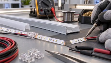
LED neon flex should be ordered by an approved assembly drawing, not by a length alone. The allowed cutting method, end caps, feed connector, cable exit and mounting detail can all change whether a segment fits. A specified illuminated length is not necessarily the same as the finished assembly length. Before ordering, confirm the exact model, dimension reference points, bend direction, termination method and electrical feed plan.
This guide is for lighting designers, contractors, sign makers and procurement teams planning low-voltage neon flex projects, including projects in Europe and North America. It explains how to turn a design into a clear quotation and sample request. It is not a cutting or wiring instruction for any specific Leomay model.
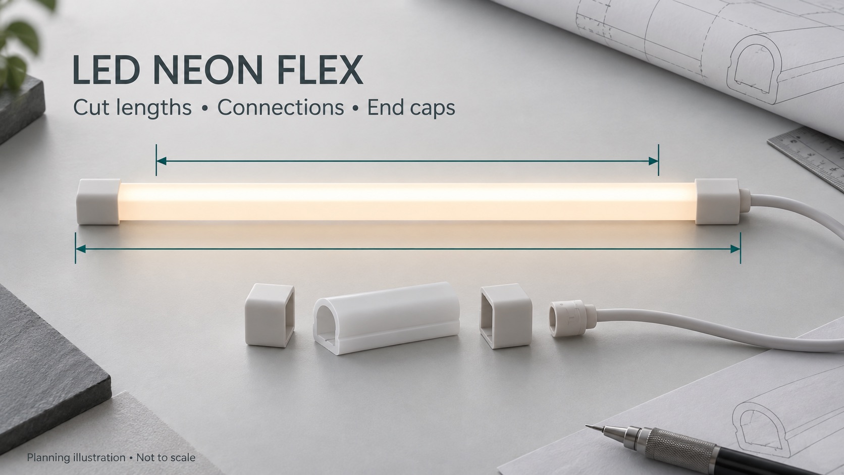
AI-generated planning illustration, not to scale and not a photograph or specification of a particular Leomay product.
“One metre of neon flex” can describe different things to a designer, supplier and installer. Separate the dimensions below instead of relying on an informal length description.
| Dimension | What to confirm on the drawing |
|---|---|
| Cut body length | The length of the neon body between the permitted cut positions, before the specified termination parts are fitted. |
| Finished assembly length | The overall envelope after the selected end caps and connector are fitted. State the reference points and whether any cable is included. |
| Illuminated length | The intended visible light line. Confirm non-luminous end zones and the appearance of joints using a representative sample. |
| Installation space | The available recess or mounting path, including room for cable routing, supports, installation access and removal. |
A connector may overlap the silicone body while also extending beyond it. Therefore, adding the full catalogue length of every part can give the wrong overall dimension. Request the assembled drawing rather than inventing a universal allowance.
When comparing silicone neon flex options, treat the cross-section, termination and mounting arrangement as part of the selection, not as accessories to decide after ordering.
Not as a general rule. Follow the cutting instructions for the exact product. A design with defined cutting increments must be cut at its permitted positions. A product explicitly designed for free cutting may follow a different procedure. Do not transfer either rule to another model because the silicone housing looks similar.
As a documented industry example, Diode LED's LINAIRE Flex Top Bend specification identifies a free-cut design and distinguishes factory assembly from field termination. Those statements apply to that product, not to Leomay products or neon flex generally.
Ask for the feasible finished dimensions before approving the order. Depending on the actual product and layout, the project may need a shorter segment, a revised mounting detail, a different model or a redesigned joint. Trimming an extra piece from an unapproved position is not a valid way to resolve a dimensional mismatch.
A factory-terminated assembly should not be assumed to be field-cuttable. Obtain the permitted modification and re-termination instructions first. Isolate power before any permitted work, and use appropriately qualified personnel. Do not cut an energised assembly or connect low-voltage DC neon flex directly to mains electricity.
A light line can be the right length but still fail to fit because its cable cannot leave the recess without being trapped. Review the cable path and connector envelope in both plan and section.
Feed orientation: request a drawing showing the cable exit relative to the illuminated face. Names such as side, bottom or end feed need a visual reference.
End treatment: identify the powered end, closed end and any segment-to-segment connection separately.
Cable clearance: allow the routing and strain relief required by the selected assembly; do not force the cable against a sharp edge.
Access: identify how the connection can be inspected or replaced after the joinery, sign or façade detail is complete.
“Left feed” is ambiguous without a viewing direction. Mark the illuminated face, cable exit and segment identification on the drawing. A mirrored installation may require a different arrangement even when its nominal segment length is identical.
A mechanically connected pair of segments does not automatically create a continuous illuminated line. End sealing, connector geometry, the position of the first light source and separation between the bodies can affect the visible joint.
Specify the required appearance, not just “no gap”. Is the light directly visible, viewed through a diffuser or reflected from a surface? Define the intended viewing distance and inspect the proposed assembly under representative brightness and ambient-light conditions. A joint that is unobtrusive in indirect lighting may be noticeable in a directly viewed sign.
Do not trim a seal, squeeze two end caps together or pull a connector to hide a dark area unless the manufacturer's instructions explicitly allow the arrangement. The better approach is to review the segment layout, approved connection option or placement of the joint before fabrication.
A straight illuminated sample cannot demonstrate the appearance of a two-segment joint. Request a representative joint assembly if visual continuity matters. Record the accepted sample configuration, lighting conditions and drawing revision so that procurement and installation use the same reference.
The outline on a drawing is not enough to establish whether neon flex can follow it. Check the model's permitted bending plane and bend limit. Do not twist the body to make a top-bend product behave like a side-bend product, or force a flexible section into an unsupported sharp corner.
For a curved installation, identify the path along which length is measured. A straight distance between endpoints is not the same as the length around the curve. Agree the dimension reference with the supplier, including whether the drawing describes the mounting centreline, an inside edge or another datum.
Use the top-bend versus side-bend neon flex guide for the mechanical selection. For a corner that cannot be formed within the selected model's limits, review a supported alternative layout rather than improvising an unapproved bend.
A segment fitting the space does not prove that the planned feed arrangement is suitable. The electrical design must separately address the selected voltage, load, controller, conductor arrangement, voltage drop and the manufacturer's permitted run configuration.
Adding a connector does not remove electrical run limits. Likewise, the longest available reel or assembly is not automatically the length that should be supplied from one feed point. Coordinate mechanical segment drawings with the electrical branch schedule.
For the electrical checks, see the voltage drop and power supply sizing guide. Do not connect independent power-supply outputs together unless the equipment documentation explicitly permits that configuration.
Compare the actual process offered for the selected model. Factory assembly can make the approved segment schedule the basis of the supplied parts; it still requires accurate drawings and dimensional acceptance criteria. Field termination can accommodate site measurements only where the product supports it, with the specified components, procedure and inspection.
Ask what changes after cutting: the permitted environment, termination method, applicable documentation and testing requirements. A sealed-looking end is not evidence that the original protection classification has been maintained. Review the LED strip IP ratings guide when water exposure is relevant.
The manufacturer's instructions are the controlling reference. For example, the LINAIRE Flex installation guide specifies its own handling and termination process. Its parts, sealing method and protection conditions must not be treated as instructions for another manufacturer's product.
For European and North American projects, identify the destination market and required product documentation at the specification stage. IP protection, electrical suitability and market conformity are separate checks. Do not treat a connector choice or a silicone housing as proof of certification for the completed installation.
Provide one schedule entry for each distinct assembly. Repeating the same nominal length with different feed orientations is not the same specification.
Identify it: drawing number, revision, segment reference and quantity.
Dimension it: required illuminated line, available installation space, agreed finished-length reference and acceptable tolerances.
Describe the shape: cross-section, illuminated face, bend direction, curve geometry and mounting method.
Define both ends: connector or end-cap type, cable-exit direction, cable requirement and access space.
Specify the lighting and supply: selected model or required colour/CCT, control method, voltage, branch arrangement and driver location.
Record the environment: indoor/outdoor location, water and cleaning exposure, target market and required documentation.
Agree acceptance: dimensional check, representative joint appearance, functional check and any project-specific verification.
Use one declared drawing unit. If both millimetres and inches are shown, identify which dimension governs; rounded conversions should not become a second conflicting specification. Keep the approved drawing and sample record together, and review substitutions against both.
Only if the exact product's instructions explicitly permit free cutting. Otherwise follow its approved cutting positions and termination procedure. Appearance alone cannot identify the internal cutting arrangement.
Do not assume it does. Ask whether the quotation describes body length, illuminated length or finished assembly length, and request a dimensioned drawing showing the included parts.
That depends on the model's cutting arrangement, assembled end details and required installation clearance. Confirm feasible finished dimensions before manufacturing the recess or approving the order.
Not necessarily. Electrical continuity and optical continuity are different. Assess the actual joint with the selected end treatment and representative viewing conditions before accepting a seamless appearance requirement.
Only within the selected product's permitted bending geometry. A sharp corner may need a revised layout or an approved connection detail; twisting or creasing the body is not a substitute.
Not automatically. The applicable rating depends on the documented assembly and termination method. Confirm the conditions for the selected product rather than assuming any sealant restores the original protection.
No. Physical fit and electrical run suitability must be checked separately using the selected product, load, wiring and supply arrangement. A connection detail cannot override those limits.
Send the drawing, segment quantities, dimensional references, bend direction, feed orientation, lighting requirements, installation environment, target market and required documents. Identify any required joint appearance or sample approval criteria.
Start with a dimensioned drawing and a clear segment schedule, not only a total metre quantity. Send your neon flex project requirements to Leomay, including the application, available space, intended light line, cable routing, selected model or lighting requirements, electrical arrangement and quantity range, so the relevant options can be reviewed.
For documentation such as UL, CE, RoHS and FCC, confirm availability and applicability for the selected specification and destination market. This guide does not claim that every Leomay neon flex model supports every cutting method, connector, protection level or certification requirement.