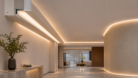
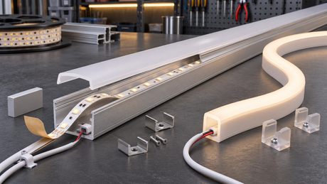
Direct answer: A dot-free linear light is created by the complete optical assembly, not by LED density alone. The visible result depends on the distance from the emitting surface to the diffuser, the spacing and shape of the light sources, diffuser material, profile geometry, viewing distance, output level, joints and installation tolerances. A higher-density SMD strip, a COB strip or a silicone neon flex can each produce a smooth line when the whole construction is matched and validated. No universal LEDs-per-metre value or profile depth guarantees a dot-free result for every project.
This guide is for lighting designers, architects, electrical contractors, joinery and display manufacturers, distributors and OEM procurement teams specifying directly visible linear lighting. It is especially relevant to European projects where compact millimetre-based details, controlled glare, replaceable components and documented sample approval are common purchasing concerns.
The search intent is both technical and commercial: buyers want to know how many LEDs per metre they need, whether COB is better than SMD, how deep an aluminum channel should be, which diffuser hides dots and what evidence should be approved before quotation or installation.
Each LED package or COB phosphor section is a light source with its own emitting area and angular distribution. A diffuser blends light only after rays from neighbouring source areas have overlapped. If the diffuser is too close, too clear or viewed from an unfavourable angle, the source pattern can remain visible. If it is moved farther away or made more diffusing, the line may become smoother, but the apparent output and line definition can also change.
This creates a design balance among four variables:
Source spacing: the distance between luminous points or zones.
Optical distance: the vertical distance from the emitting surface to the inside of the diffuser.
Diffusion: how strongly the cover scatters and redistributes light.
Viewing condition: distance, angle, brightness and surrounding surface reflectance.
Changing only one variable can solve one problem and create another. For example, a stronger diffuser may reduce visible points while reducing apparent brightness. A deeper profile may improve blending but may not fit the architectural recess. A denser strip may improve continuity but still show a line of brighter zones through a shallow or clear cover.
For an evenly spaced SMD strip, the approximate pitch in millimetres can be calculated as:
LED pitch (mm) = 1,000 ÷ LEDs per metre
This calculation helps compare source spacing, but it is not a dotless guarantee. Two strips with the same LEDs per metre may use different package sizes, optical distributions, PCB layouts, output levels or colour configurations. RGB, RGBW and multi-channel products may also place different emitters within one package or sequence, so the visual pattern can change with the selected scene.
Use pitch to begin the cross-section review, then compare the actual strip drawing, profile cavity, diffuser position and intended viewing condition. The LED strip specification guide explains why density should be evaluated with voltage, power, colour, cut length, control and installation rather than as an isolated headline number.
A shallow profile keeps the overall detail compact, which can be useful in furniture, shelving and narrow architectural reveals. The trade-off is limited blending distance. The diffuser is close to the emitters, so individual points, bright bands or colour separation can become more visible. A shallow profile therefore needs careful coordination among source construction, density, diffuser and viewing distance.
A deeper cavity gives light more distance to spread before reaching the diffuser. This can improve uniformity, but depth alone is not enough. Internal reflections, side-wall shape, strip position and diffuser characteristics still influence the result. The extra depth may also affect recess dimensions, end caps, mounting clips and service access.
Do not compare profiles only by their external height. The relevant optical distance begins at the emitting surface and ends at the inside face of the diffuser. The PCB mounting shelf, strip thickness, component height and lens engagement all reduce the usable cavity. Request a cross-section drawing and compare the selected strip and profile at the same scale.
An opal or frosted diffuser scatters light to soften the source pattern. Its result depends on material, thickness, surface treatment, curvature and distance from the strip. “Opal” is not one universal optical specification, and two covers that look similar when unlit can produce different uniformity and apparent output.
Evaluate the diffuser for the real project question:
Is the luminous face viewed directly or through reflection?
At what distance and angle will users see it?
Must the line be narrow and defined or wide and soft?
Is maximum apparent output more important than perfect visual blending?
Will the installation be dimmed to low levels where source patterns may change?
A clear or lightly frosted lens can retain more source definition. A stronger diffuser can improve visual mixing but may alter the amount and distribution of visible light. Approve the complete lit assembly; do not select a cover by colour or catalogue name alone.
SMD strip can suit many profile systems and can provide clear component-level serviceability. A dense layout reduces the distance between sources, but the final line still depends on package size, profile depth and diffuser. SMD may remain a strong choice when the source is not viewed at very close range, when a specific package or channel arrangement is required, or when the approved profile provides sufficient blending distance.
COB strip uses a more continuous phosphor-covered emitting area and is often evaluated for slim profiles or close viewing. It can reduce the obvious point pattern associated with discrete packages, but “COB” does not mean every installation will be perfectly uniform. Local brightness variation, shallow lens distance, reflective surfaces, joins and control behaviour can still affect the appearance. Review COB versus SMD LED strip as a system decision rather than a simple quality ranking.
Silicone neon flex places the light source inside a shaped diffusing body. The cross-section defines the luminous face, bend direction and much of the optical distance. It can be appropriate when the luminous body itself is visible or the design includes planned curves. It also requires space for the full body, mounting channel or clips, cable exit, cut position and end treatment. A generic silicone sleeve should not be assumed to fit or optically match every bare strip. Compare the selected cross-section and assembly method.
For a broader mechanical comparison, see the COB strip versus LED neon flex guide.
A sample that appears continuous from two metres away may show points at close range. A line viewed straight through the diffuser may look different from the same line seen at a shallow angle along its length. Glossy joinery, mirrored surfaces and polished stone can reveal source patterns that are not obvious on a matte surface.
Define the critical viewing positions before choosing the assembly. For cabinets and shelves, inspect seated and standing eye levels. For retail displays, include the nearest customer position. For wall or ceiling details, consider entrances, stairs and upper floors. For reflective interiors, inspect both the luminous face and its reflection.
A straight centre section is usually the easiest part of the sample. Dark gaps and bright overlaps often appear at cut points, connectors, cable feeds, profile joints, end caps and corners. The strip cut increment may prevent a luminous section from ending exactly where the profile or drawing ends.
Show the following on the installation drawing:
strip cut positions and the first emitting area after each cut;
connector or soldered-lead space inside the profile;
profile and diffuser joint locations;
cable feed and exit directions;
corner method and permitted bending plane;
service access for replacement sections.
Do not hide a dark joint by stressing a strip, trimming an unapproved sealing part or overlapping sections without review. Move the joint, change the approved connection method or revise the detail. For general fit checks, use the LED strip and aluminum profile compatibility guide.
A visually smooth line can still be electrically or thermally unsuitable. Confirm the selected model's voltage, power per unit length, total connected load, feed points, cable size, control method and mounting conditions. The profile can support alignment, diffusion and heat spreading when the strip and installation interface are suitable, but it is not an automatic thermal solution.
Do not choose a higher-density or higher-power strip only to hide dots. First determine the required light level and visual effect, then review the heat path and electrical layout. The LED strip thermal management guide explains how profile contact, mounting surface and operating conditions form one system.
Define the visible result. State whether the line is directly visible, reflected or hidden, and from what distance.
Fix the available cross-section. Record the maximum width, depth, flange and service clearances.
Select the source family. Compare SMD strip, COB strip and neon flex against the geometry, curve and maintenance plan.
Compare the actual drawings. Check strip width, component height, emitting position, diffuser distance and termination space.
Review electrical and thermal conditions. Confirm load, feed plan, control, cable route and heat path.
Build a representative sample. Use the intended strip, profile, diffuser, connector, end cap, driver and control setting.
Approve from real viewing positions. Inspect full and dimmed output, joints, corners, reflections and service access.
Record the approved assembly. Keep model references, revisions, cross-sections, sample photos and installation notes together.
A useful sample should include more than a short centre section. Ask the project team to check:
uniformity at the nearest and normal viewing distances;
appearance from the side and along the line;
full output and the lowest expected dimming level;
one representative joint, cut or cable-feed transition;
one corner or curve when the project includes one;
diffuser closure, end-cap fit and cable clearance;
alignment, mounting retention and service access;
operation under the intended driver and control method.
Record camera exposure if photos will be used for approval, because automatic exposure can hide or exaggerate dots. The visual decision should be made by observing the real sample under representative ambient light.
There is no universal number. Calculate the source pitch, then evaluate package size, profile depth, diffuser, output and viewing distance. Approve the exact assembly in a sample.
No. COB construction can reduce visible points, but shallow optical distance, joins, reflective surfaces and close viewing can still reveal variation. The complete assembly determines the result.
The required depth depends on source pitch, emitting area, diffuser and viewing conditions. Use the internal optical distance rather than the profile's outside height, and validate the selected cross-section.
Not automatically. Diffuser material and geometry can improve mixing, but insufficient distance, large source spacing, joints or reflections may remain visible.
Sometimes higher density improves continuity, but it does not reproduce every optical effect of additional blending distance. Compare both options for appearance, available space, output, heat and cost before approval.
Yes, when package spacing, profile depth, diffuser and viewing conditions are matched. SMD should not be rejected only because the LEDs are discrete.
No. The strip width, emitting direction, heat path, bend direction, cut positions, cable exit and sleeve construction must be compatible. Confirm the exact assembly rather than using a generic family description.
Send the application, viewing distance, cross-section drawing, available width and depth, selected strip or preferred source family, profile and diffuser preference, line lengths, joints and corners, voltage, colour or CCT, CRI, control method, environment, quantity range, target market and required documentation.
Planning a directly visible linear-lighting project? Send Leomay the application, critical viewing positions, cross-section drawing, available dimensions, intended LED strip, COB strip or silicone neon flex format, profile or sleeve, diffuser preference, line lengths, joints, corners, voltage, colour or CCT, CRI, control method, environment, quantity range, target market and required documentation. Leomay can review relevant product and profile options for the selected project. Final compatibility, performance and document availability must be confirmed for the exact model and configuration.