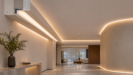
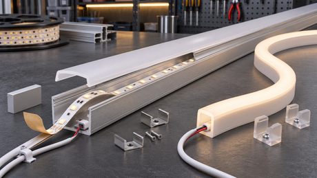
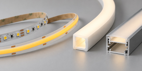
Direct answer: Start a recessed linear-lighting specification by defining what the finished detail should show: reflected light from a concealed source, a visible continuous luminous line, or a curved architectural outline. Then select the LED strip, COB strip, silicone neon flex, aluminum profile, diffuser, wiring route, and service method as one assembly. The product format should follow the section drawing and viewing condition, not the product name alone.
What This Guide Helps Buyers Decide
This guide is for lighting designers, architects, fit-out contractors, electrical installers, distributors, and OEM procurement teams comparing components for recessed ceilings, wall reveals, shelves, joinery, display features, and curved architectural lines.
Its purpose is product and assembly selection. It does not provide a universal recess dimension or promise a particular visual result. Final suitability depends on the selected model, the installation section, the target market, and a representative sample built with the intended components.
First Define the Finished Lighting Detail
“Recessed linear lighting” can describe several different outcomes. A concealed strip may illuminate a ceiling or wall without being directly visible. A trimless channel may create a visible line within plasterboard or joinery. A silicone neon profile may form a curved or exposed outline. These details require different mechanical and optical decisions.
Concealed reflected light
The viewer mainly sees light on a ceiling, wall, shelf, or cabinet surface. Selection should focus on the direction of emission, available mounting plane, distance to the receiving surface, access route, and the effect of the actual finish.
Visible recessed luminous line
The diffuser or luminous surface remains visible. The width of the opening, profile depth, diffuser position, strip alignment, joint treatment, and viewing distance become part of the visual specification.
Curved or shaped outline
The lighting follows a radius, contour, sign, or architectural boundary. Confirm the permitted bend direction, cross-section, mounting method, cable exit, end treatment, and whether the complete route can be installed and serviced.
Selection Matrix: Which Product Format Fits the Detail?
| Format | Typical reason to consider it | What must be confirmed |
|---|---|---|
| Conventional LED strip | Flexible source for concealed straight runs, shelves, joinery, and profile-based assemblies | PCB width, voltage, color or CCT, LED spacing, cut unit, control method, mounting surface, and profile compatibility |
| COB LED strip | A more continuous-looking source is important at the intended viewing distance | Actual luminous appearance, width, power and thermal conditions, cut unit, profile and diffuser, and control compatibility |
| Silicone neon flex | A visible, protected, curved, or clearly defined luminous outline is required | Cross-section, bend direction, minimum route geometry, cut and connection method, cable exit, end caps, brackets, and environmental requirement |
| LED aluminum profile | A repeatable mounting channel, diffuser position, defined opening, protection during installation, or serviceable assembly is needed | Internal width, depth, trim condition, diffuser, end caps, mounting method, strip fit, cable space, and access |
The matrix is a starting point. A buyer should compare complete candidate assemblies rather than approve an isolated strip, diffuser, or sleeve from a catalogue image.
When Conventional LED Strip Is a Practical Starting Point
Conventional low-voltage LED strip is a flexible option for concealed straight runs and profile-based details. It can suit shelves, cabinets, wall reveals, recessed channels, and other applications where the section provides enough space for mounting, wiring, and access.
Provide the required voltage, color or CCT, CRI target, PCB width, cut unit, control method, run lengths, and installation environment when requesting a recommendation. LED package and density are useful identifiers, but they do not replace a review of the complete assembly.
Buyers can use the LED Strip collection to identify candidate formats before confirming model-level compatibility.
When COB Strip May Better Match the Visual Brief
COB strip may be considered when the source or diffuser is visible and the brief calls for a smoother luminous appearance. This can be relevant in shallow recessed lines, joinery details, display lighting, and profile assemblies viewed from a shorter distance.
COB construction does not remove the need to check profile dimensions, diffuser transmission, heat path, voltage, control method, and sample appearance. The complete selected combination should be reviewed under the intended viewing condition.
Compare available formats in the COB Strip collection, then confirm the exact model and assembly requirements.
When Silicone Neon Flex Is the Better Mechanical Choice
Silicone neon flex can be useful when the visible feature is a defined luminous outline, when the route is curved, or when a flexible outer body is preferable to a rigid aluminum channel. It should be specified as an assembly that includes the luminous body, connectors or cable entries, end treatment, brackets or channel, and installation surface.
Top-view and side-view products bend in different directions. The drawing should show the route, bend plane, starts and ends, cable direction, joints, corners, and accessible connection points. Do not assume that a body rating automatically applies to every connector, end cap, cable entry, power supply, or completed installation.
Review the Silicone Neon Flex collection as a category reference and confirm the required section with the project drawing.
What the Aluminum Profile Must Coordinate
An LED aluminum profile is part of the mechanical and optical assembly. It can establish the strip position, hold a diffuser, define the visible opening, protect components during installation, and provide a repeatable mounting detail. It also affects the available internal width, cable space, diffuser distance, and service method.
For recessed work, confirm whether the profile is inserted into joinery, fixed within a prepared channel, or coordinated with a ceiling or wall system. Review the actual internal dimensions rather than only the external appearance. The selected strip, connector, cable, diffuser, end cap, and mounting hardware must fit together.
Use the Aluminum LED Profile collection to compare profile families, then verify the selected cross-section against the strip and construction detail.
Coordinate Mechanical Fit Before Electrical Selection Is Final
Record the opening width, available depth, mounting plane, access panel, cable-entry direction, joint positions, corner conditions, and the surface receiving the light. These constraints can eliminate a product format before voltage or output is discussed.
A recessed assembly also needs a realistic installation sequence. Confirm whether the strip or neon body can be inserted after finishes are complete, whether connectors can pass through the opening, and whether a failed component can be inspected or replaced without damaging the surrounding construction.
Then Match Voltage, Control, and Feed Layout
After the mechanical route is defined, confirm input voltage, run lengths, feed points, conductor route, polarity, controller or dimmer type, channel configuration, and power-supply access. The control architecture must match the selected product; a profile or silicone body does not prove electrical compatibility.
For tunable-white, RGB, RGBW, RGB+CCT, or addressable systems, document the required channel or signal arrangement and connector method before ordering. Model availability, technical documentation, and approvals should be checked for the selected product and destination market.
Indoor, Damp, and Outdoor Conditions Change the Assembly
Classify the environment before final selection. A dry indoor joinery channel, a condensation-prone recess, an exterior soffit, and a landscape outline have different requirements for the light source, profile or sleeve, joints, end caps, cable entries, power supply, mounting hardware, and drainage.
Review the complete installed system rather than extending one component's IP code or document set to every part of the project. Required certification documentation and applicability must be confirmed for the exact model and target market.
Build a Representative Selection Sample
A useful sample reproduces the project variables that influence fit and appearance. Include the proposed strip or COB strip, profile or neon section, diffuser, connector or cable entry, mounting surface, finish, control method, and intended viewing distance.
Confirm that the light source, cable, connector, and diffuser physically fit the section.
Check insertion, fixing, end treatment, joint alignment, and removal for service.
View the assembly from the normal standing, seated, or walking positions.
Test the intended control mode and representative operating levels.
Record the approved product model, section, accessories, wiring method, and sample photographs.
Information to Send for Product and Sample Review
Application: recessed ceiling, wall reveal, shelf, joinery, display, curved outline, or another detail.
Section drawing with opening, depth, mounting plane, route, corners, and access points.
Whether the viewer sees reflected light, the diffuser, or the complete luminous surface.
Preferred format, if known: LED strip, COB strip, silicone neon flex, and/or aluminum profile.
Voltage, color or CCT, CRI target, control method, run lengths, and feed plan.
Indoor, damp, or outdoor condition; target market; quantity range; and required documents.
Photos, drawings, or a physical-section reference showing the finish and installation constraints.
Frequently Asked Questions
Is recessed linear lighting always made with an aluminum profile?
No. Some details use a profile-based LED strip or COB assembly, while others use silicone neon flex or another project-specific mounting method. Select the format from the section, visible effect, route, and service requirement.
Should I select the strip or the profile first?
Define the installation section first, then shortlist compatible strip and profile combinations. Internal width, depth, diffuser, connector space, cable route, and mounting method must be checked together.
Is COB strip required for every visible recessed line?
No. COB may suit a smoother visible source, but the final result also depends on the profile, diffuser, viewing distance, alignment, and operating condition. Compare complete samples.
When should I consider silicone neon flex instead of LED strip?
Consider neon flex when the project needs a visible defined outline, a curved route, or a flexible outer luminous body. Confirm its cross-section, bend direction, connection method, and mounting system.
Can one product be used for straight and curved recessed details?
Not automatically. Straight rigid channels and curved outlines impose different mechanical constraints. Share the full route and bend directions so the candidate sections can be reviewed.
What dimensions are most important on the drawing?
Show the visible opening, available depth, mounting plane, route radius where applicable, cable-entry space, joint and corner locations, and service access.
Does an IP rating cover the finished recessed installation?
No. The completed system includes joints, connectors, end caps, cable entries, power supplies, mounting surfaces, and installation workmanship. Review every relevant component and exposure condition.
What should I provide before requesting a quotation or sample?
Provide the application, section drawing, viewing condition, preferred format, voltage, color or CCT, control method, run lengths, installation environment, target market, quantity range, and required documents.
Review the Complete Recessed Assembly With Leomay
For a product and sample review, send Leomay the section drawing, application, viewing condition, preferred light-source format, voltage, color or CCT, control method, run lengths, profile or neon requirements, installation environment, target market, quantity range, and required documentation. Leomay can review compatibility requirements for the selected product and project; final model availability and document scope should be confirmed for the specific request.
For project questions, use the Leomay contact page and include drawings or reference photos where available.